

PARALLEX Synchronized Hydraulic Cylinders
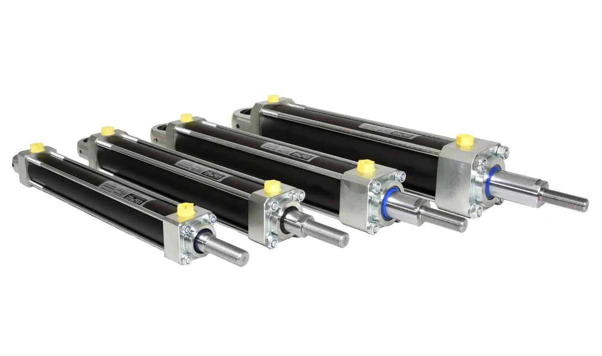
With PARALLEX, you can have up to six tie-rod cylinders operate in synchronized motion without a flow divider—ensuring the right level and the right load-bearing capacity, regardless of how the load is distributed.
A good alternative to a flow divider
PARALLEX is based on the volume ratios between hydraulic cylinders of different sizes connected in series. The system replaces flow dividers and provides a simpler, safer solution for synchronized movements.
The cylinders automatically calibrate themselves every time they reach an end position—no external adjustment is needed. The design is of the tie-rod type with no welded joints, making it well-suited for demanding applications involving vibrations and pressure surges.
In most cases, a PARALLEX system is much simpler and safer than a flow divider.
Why PARALLEX?
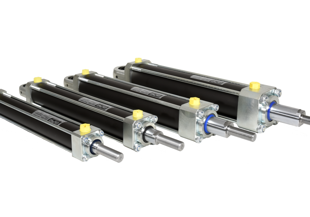
Simpler and safer than a flow divider—developed and proven by Lalmek.
-
Parallel movement regardless of off-center loading
The cylinders maintain the level even under uneven loads.
-
No external components
A simple system without a flow divider or external control.
-
Single-acting or double-acting
Select the model that best suits your needs.
-
Holds the load in place
Maintains parallelism in a stationary position.
-
Self-calibration at end positions
Automatic adjustment with every stroke.
-
Push, pull, or lift
Flexible use.
-
2–6 cylinders in parallel
Scalable without increased complexity.
-
Reliable and Affordable
Few components and automatic calibration ensure a long service life and a low total cost of ownership.
Suitable Applications
PARALLEX is suitable for applications with high requirements for synchronized movements.
Material Handling
Lifting systems for material handling where smooth and synchronized movement is essential.
Vehicle Assembly
Assembly platforms and lifting systems for the automotive industry.
Height-adjustable workstations
High-precision, adjustable workstations for industrial use.
Hydraulic presses
Presses that require even force distribution across the entire surface.
Production Equipment
Industrial equipment in which synchronized movements are critical to the process.
Special Applications
Customized solutions for unique requirements regarding parallelism and load-bearing capacity.
Size Chart
The cylinders are available in 16 standard sizes ranging from 25/16 to 250/150 mm. A complete dimensional drawing is provided upon request for a quote. We reserve the right to make design changes.
| Dimension | Maximum pressure (bar) | Push force at 200 bar (metric tons) | Pull force at 200 bar (metric tons) | Internal cylinder diameter (mm) | Piston Rod Diameter (mm) | |
|---|---|---|---|---|---|---|
| 25/16 | 300 | 1.0 | 0.6 | 25 | 16 | Request a quote |
| 32/20 | 260 | 1.6 | 1.0 | 32 | 20 | Request a quote |
| 40/24 | 290 | 2.5 | 1.6 | 40 | 24 | Request a quote |
| 40/30 | 290 | 2.5 | 1.1 | 40 | 30 | Request a quote |
| 50/30 | 200 | 3.9 | 2.5 | 50 | 30 | Request a quote |
| 60/33 | 200 | 5.7 | 3.9 | 60 | 33 | Request a quote |
| 60/40 | 200 | 5.7 | 3.1 | 60 | 40 | Request a quote |
| 70/36 | 230 | 7.7 | 5.7 | 70 | 36 | Request a quote |
| 80/39 | 200 | 10.1 | 7.7 | 80 | 39 | Request a quote |
| 80/60 | 200 | 10.1 | 4.4 | 80 | 60 | Request a quote |
| 100/60 | 200 | 15.7 | 10.1 | 100 | 60 | Request a quote |
| 100/75 | 200 | 15.7 | 6.9 | 100 | 75 | Request a quote |
| 125/75 | 210 | 24.5 | 15.7 | 125 | 75 | Request a quote |
| 160/100 | 250 | 40.2 | 24.5 | 160 | 100 | Request a quote |
| 200/120 | 290 | 62.8 | 40.2 | 200 | 120 | Request a quote |
| 250/150 | 300 | 98.2 | 62.8 | 250 | 150 | Request a quote |
(1) Size + stroke length
(2) Other measurements upon request
(3) The piston rod is machined to order in all available configurations
We reserve the right to make design changes.
Installation and Commissioning
Follow these steps for proper installation. Be extremely careful to ensure that no contaminants enter the system.
Pipe Selection
Use thick-walled hydraulic pipes with as small an internal diameter as possible, taking into account the pressure drop in the lines. If it is not possible to use hydraulic pipes the entire way, double-reinforced hydraulic hoses can be used for the necessary sections—however, this will result in reduced parallelism.
These measures reduce the misalignment between the cylinders caused by the elasticity of the oil, the lines, and the cylinder tubes. When lifting a table, position the cylinders as far out toward the corners as possible to avoid amplifying the slight misalignment that occurs regardless.
Preparation
Clean and inspect each hose after cutting. Inspect each adapter before use. Do not remove the plugs from the hydraulic cylinders until the hoses are ready to be installed.
Assembly Steps
Exhaust Ventilation
Basic
Please note that the cylinders should be operated without being mounted during startup. They do not move in parallel when there is air in the system.
- Turn the cylinder so that the piston rod is pointing up or down, not horizontal.
- Move the cylinders to their end positions, and let the pump run for 60–120 seconds at 30–50 bar.
- Turn the knob all the way to the other end and let it run for about 60 seconds.
- Repeat a couple of times.
- During the final venting, increase the pressure to a maximum of 200 bar.
Vertical, piston rod pointing upward
Inject oil into the positive side of the largest cylinder. When the piston rod reaches its upper dead center, a bypass to the next cylinder opens. Continue until all cylinders have reached their upper end position—then maintain the oil pressure for another 3–5 minutes so that any trapped air has time to flow back to the oil tank.
Bleeding may take 10–50 minutes, as the bypass valve allows approximately 0.5 liters of oil to pass through per minute. Reduce the pressure at the pressure relief valve to 50 bar during bleeding to prevent the oil from overheating.
Vertical, piston rod pointing down
Bleed the system in reverse order. Apply oil pressure to the negative side of the smallest cylinder until oil free of air flows out of the positive side of the largest cylinder.
Horizontal
Air is vented through the bypass in the cylinder tube. For the venting to work, the bypass must face upward—it is marked in red on the cylinder tube. By default, it is located on the same side as the threaded connections. When ordering, specify how the connections should be positioned, or adjust the cylinder by loosening the tie rods and rotating the cylinder tube.
Important!
To maintain the system's parallel motion pattern and compensate for internal microleaks, the cylinders must reach one of their end positions at least once every 20 to 100 strokes.
Hydraulic Diagram
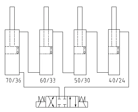
The figure shows a hydraulic diagram for series-connected hydraulic cylinders with a compensation function. In most cases, a PARALLEX system is much simpler and safer than a flow divider.
The cylinders are available with several mounting options at both the piston rod end and the cylinder end:
The piston rod can be machined to any standard configuration upon request. As an option, the system can be equipped with built-in linear encoders for high-precision measurement of the piston rod’s position.
Frequently Asked Questions About PARALLEX
Interested in PARALLEX?
Contact us for advice, a quote, and technical support.